


Installation of Two 5-Ton Steel and Cast Iron
Induction Furnaces in the Great Lakes, USA
Table of Contents
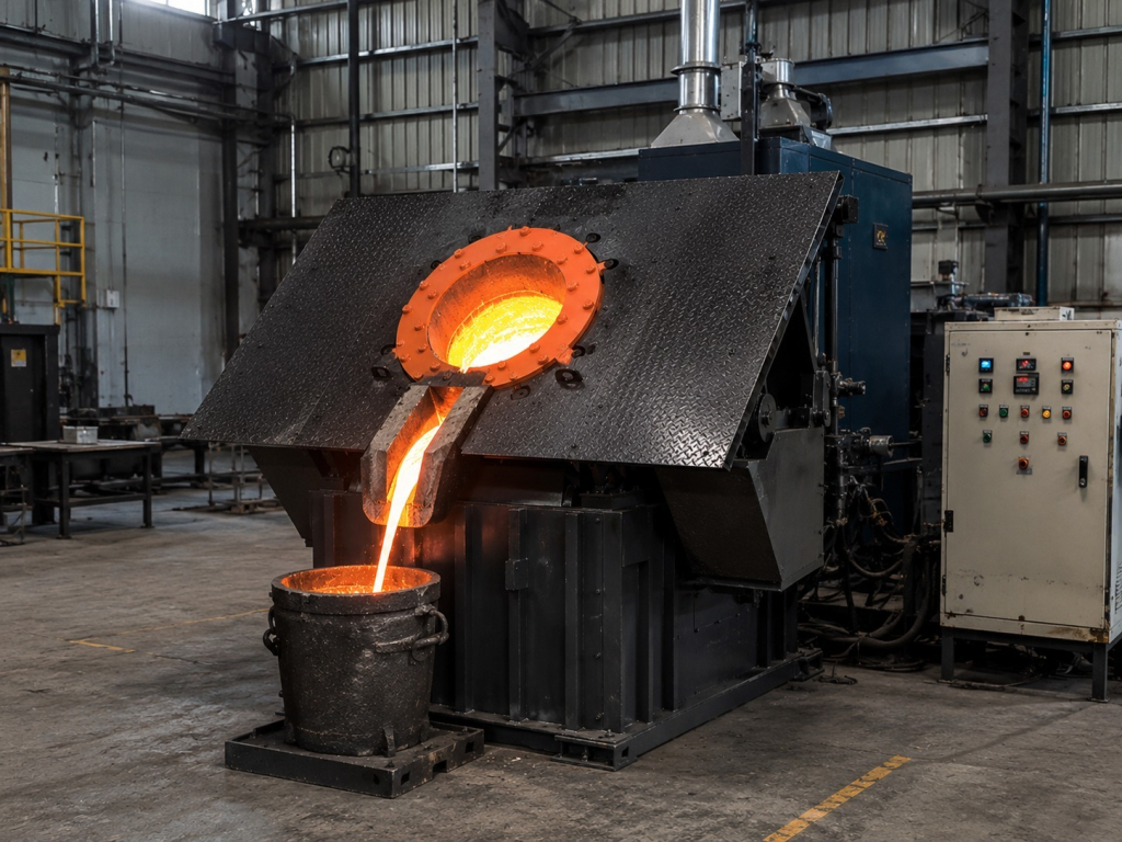
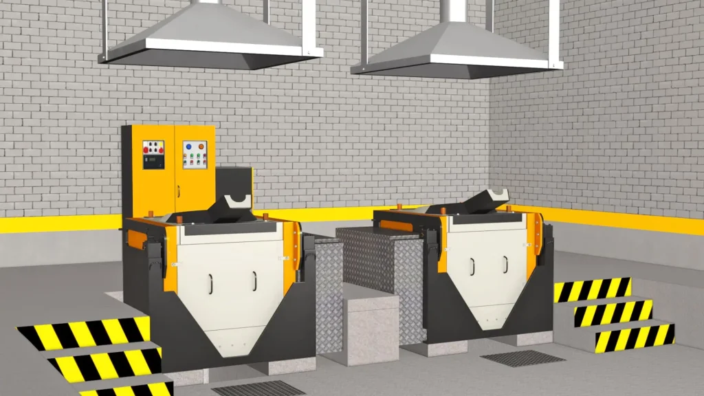
control cabinet, hydraulic units, cooling connections, and overhead fume extraction for steel and cast iron melting.
A foundry specializing in steel and cast iron in the Great Lakes region required a dependable melting line to handle various materials such as mild steel scrap, cast iron returns, pig iron, sprues, risers, and alloy additions. Electroheat delivered, installed, and commissioned a twin-furnace coreless induction setup with two 5-ton vessels, hydraulic tilting, PLC/HMI controls, demineralized-water cooling, overhead fume extraction, and data logging for long-term operation. Due to confidentiality concerning the client’s identity and sensitive production data, this case study focuses on the system configuration, the commissioning process, and the observed qualitative improvements at handover.
Project at a Glance
| Project Item | Installed Details |
| Client | Confidential steel and cast iron foundry |
| Location | Great Lakes region, United States |
| Installed system | Two 5-ton coreless induction melting furnace bodies in a twin-furnace arrangement |
| Primary materials | Mild steel scrap, cast iron returns, pig iron, sprues, risers, and alloy additions |
| Melting duty | Repeated batch melting for foundry production |
| Power technology | Insulated-gate bipolar transistor (IGBT) medium-frequency power supply |
| Controls | Programmable logic controller (PLC) with human-machine interface (HMI), alarms, trips, interlocks, and heat records |
| Pouring arrangement | Hydraulic tilting for controlled tapping |
| Cooling and extraction | Demineralized (DM) water circulation, cooling support, and overhead fume-extraction hoods |
| Data visibility | Power, kWh, heat time, alarm history, trip logs, and shift or production reports |
Watch the Steel Induction Melting Furnace in Operation

The Foundry Challenge
The foundry processed a charge mix that varied from heat to heat. Dense pig iron, loose steel scrap, cast iron returns, sprues, risers, and alloy additions did not load or melt consistently. The plant needed a furnace arrangement that could accept these variations without treating each heat as a new operating experiment.
Production planning created a second challenge. Repeated heats had to be coordinated with tapping, refractory inspections, cooling-system checks, and routine maintenance. A single-vessel workflow would have left less room to organize these activities. The foundry therefore needed two furnace bodies, a stable power and control platform, and a pouring system suited to heavier batches.
Process visibility was also limited. Operators needed a clearer view of furnace power, heat time, cooling status, alarms, and interlocks. Maintenance staff needed fault information to pinpoint the affected circuit, rather than resorting to trial-and-error troubleshooting. Consequently, the project brief covered the entire melting line rather than the furnace shell alone.
Site Review and Furnace Selection
Electroheat began with a technical review of the foundry’s production route. The review covered charge materials, planned batch size, heats per shift, transformer readiness, incoming power, water quality, cooling capacity, refractory practice, tapping method, floor space, extraction, and operator access. These checks established the duty the furnace line was expected to perform and the plant services required to support it.
Why a twin coreless arrangement
A coreless design was selected because the foundry required batch melting, frequent charging, grade flexibility, and complete tapping between heats. Unlike a channel furnace, commonly used for holding molten metal or for steady, continuous duty, a coreless furnace places the refractory-lined vessel inside the induction coil. It is well suited to scrap melting and individual heat control.
The twin-furnace arrangement provided two 5-ton furnace bodies within a coordinated melt-shop layout. This gave the operating team greater flexibility in sequencing melting, tapping, lining inspection, and maintenance. The two vessels were coordinated within the installed power system, with their operating sequence determined by the foundry’s production schedule, power availability, and melt-shop workflow.
Engineering review priorities
The final selection was based on more than vessel capacity. Electroheat matched the furnace bodies to the charge profile, hydraulic tapping requirements, power and transformer conditions, cooling load, control philosophy, and available floor layout. Overhead extraction hoods were incorporated into the layout to capture fumes above the furnace stations and keep the work area organized.
At Electroheat, we select a steel or cast-iron melting system based on its full operating duty, not just tonnage. Factors like charge composition, refractory approach, transformer capacity, cooling stability, and tapping method influence the system’s reliability over multiple heats.
Mr. Charlie, Chief Engineer, Electroheat Induction
The Electroheat System Installed
Furnace and power package
Electroheat installed two 5-ton coreless furnace bodies with induction coils, refractory working zones, a capacitor bank, a power cabinet, bus and cable connections, and hydraulic tilting equipment for foundry duty. The IGBT power supply converted the incoming electrical supply into a controlled medium-frequency output for the induction circuit and responded to the changing electrical characteristics of the charge as it moved from packed scrap to a molten bath.
Control, data, and protection
The PLC/HMI control package provided operators with a graphical view of furnace status and key electrical values. The system recorded power, kWh consumption, heat time, alarms, trips, and interlock activity. Long-term heat and shift records provided supervisors with a traceable operating history, while diagnostic navigation helped maintenance staff more quickly distinguish among cooling, electrical, hydraulic, and interlock events.
Cooling, hydraulic tilting, and extraction
Demineralized water circulation and cooling protected the induction coils, capacitor bank, power electronics, and other water-cooled components. Flow, temperature, and protective interlocks were monitored as part of the operating logic. Each furnace body was fitted with hydraulic tilting, allowing the operator to control the furnace angle and discharge during tapping. The overhead hoods completed the melt-shop arrangement by providing extraction directly above the furnace stations.
| Installed Component | Project Function |
| Two 5-ton furnace bodies | Provided a twin-vessel layout for repeated steel and cast iron batch melting |
| IGBT power supply | Delivered controlled medium-frequency power as charge conditions changed |
| Induction coils and refractory zones | Generated heat within the charge and contained the molten metal |
| PLC/HMI control system | Displayed operating status, electrical values, alarms, trips, interlocks, and heat records |
| Hydraulic tilting units | Supported steady furnace movement and controlled tapping |
| DM-water cooling arrangement | Removed heat from coils, capacitors, power electronics, and water-cooled circuits |
| Data logging and reporting | Created a history of kWh, heat activity, shift production, alarms, and trips |
| Overhead extraction hoods | Captured fumes above the furnace stations and supported a cleaner work area |
Installation and Commissioning
Equipment placement and service connections
The installation team positioned the two furnace bodies, aligned the hydraulic mechanisms, and located the power and control cabinet within the melt-shop layout. Power cables, cooling water lines, hydraulic connections, furnace selection circuits, and auxiliary services were routed to ensure access for operation and maintenance. The extraction hoods were aligned above the furnace stations before hot commissioning.
Pre-start verification
Before the first heat, the team verified transformer and electrical readiness, grounding, emergency stops, cooling-water flow, temperature and conductivity protection, hydraulic movement, PLC/HMI communication, alarms, trips, and interlocks. The refractory condition and furnace body alignment were also checked. The system was not released for melting until the protection chain responded correctly.
Trial heats and operator handover
Supervised trial heats were then used to confirm charging practices, power ramp-up, melt observation, temperature correction, tapping, and shutdown. Operators were trained in HMI navigation, alarm response, cooling checks, hydraulic control, record review, and daily inspection. This stage converted the installed equipment into a functioning production line and provided the customer with a repeatable operating routine.
Results After Commissioning
The commissioning review confirmed that the twin-furnace line met the project’s primary operational objectives. The foundry gained a defined route for melting mild steel and cast iron charges, clearer visibility into furnace condition, and a more orderly tapping process. The second furnace body also gave the melt-shop team greater flexibility to schedule heats, lining work, and maintenance without treating every interruption as a full-line event.
Operators could now monitor power, heat time, cooling conditions, alarms, trips, and interlocks from the HMI rather than relying solely on visual observation. Maintenance personnel gained access to a stored event history for fault review, and supervisors had access to kWh and heat records for operating discussions. These changes did not eliminate the need for disciplined charging, refractory care, and cooling checks; they gave the team better tools to manage these tasks.
Commercial melt-time, energy-per-ton, and shift-output figures remain confidential. The published results therefore focus on the process control, maintenance, and operating improvements verified during commissioning and initial operation.
| Before the Project | After Commissioning |
| A changing charge mix was difficult to manage through one consistent routine | The twin-furnace line, comprising two 5-ton furnace bodies, was commissioned for mild steel, cast iron returns, pig iron, sprues, risers, and alloy additions. |
| Operators had limited visibility of the furnace and cooling conditions | The HMI displayed power, heat time, cooling status, alarms, trips, and interlocks |
| Heavy tapping required a more stable discharge method | Hydraulic tilting provided controlled furnace movement and pouring |
| Fault review depended heavily on manual troubleshooting | Stored alarm, trip, and interlock records gave maintenance staff a clearer diagnostic trail |
| Maintenance planning was mainly reactive | Heat records, kWh data, daily checks, and spare-parts planning supported a more structured maintenance routine |
Why the Project Configuration Worked
The project succeeded because the furnace line was treated as an integrated production system. The twin-furnace arrangement supported more flexible batch scheduling; the IGBT platform stabilized electrical power delivery; the PLC/HMI improved process visibility; the DM-water circuit protected thermally loaded components; hydraulic tilting improved tapping control; and the extraction hoods supported the physical melt-shop environment.
No single feature delivered the result on its own. The value came from aligning furnace size, electrical supply, cooling, refractory practice, controls, pouring, and operator training with the same production objective. That systems approach is the main lesson for foundries planning a similar steel and cast-iron melting installation.
Related Electroheat Equipment and Support
Projects of this scale typically require coordinated selection of the furnace, power supply, cooling, transformer, controls, spares, and technical services. Relevant Electroheat solutions include:
- Steel Induction Furnaces
- Cast Iron Induction Furnaces
- Induction Melting Furnaces
- Cooling Towers and DM-Water Systems
- Power Transformers
- Induction Furnace Spare Parts
- Foundry and Mining Furnace Consulting
Request a Steel or Cast Iron Furnace Recommendation
Electroheat can review your metal type, charge materials, required batch size, heats per shift, available power, transformer capacity, cooling-water conditions, floor layout, and tapping method before recommending a furnace configuration. Share your project requirements to receive guidance on furnace capacity, power supply, cooling, controls, hydraulic tilting, installation scope, and spare parts planning.